

The relay module is the board most people actually buy to switch a load from a microcontroller. It takes a bare mechanical relay and adds the parts you would otherwise have to wire yourself: a driver transistor, a flyback diode, an optocoupler for isolation, and a status LED, all behind a clean logic-level input. They come in one, two, four, eight, and sixteen channel sizes, so one board can switch a whole bench of grow lights, heat mats, and pumps.
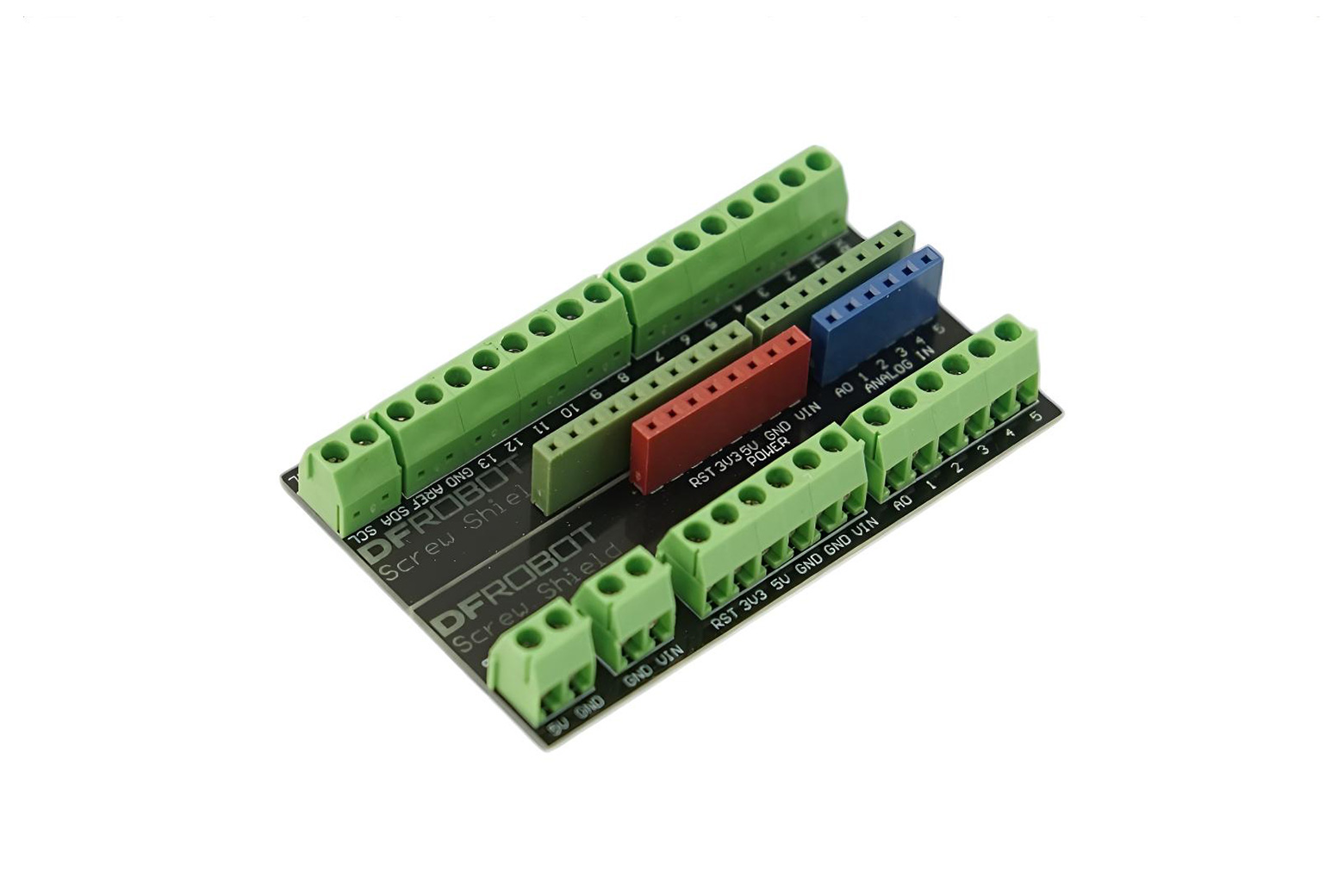
What it is.
Each channel is a relay with everything it needs to be driven safely from a logic pin. The transistor handles the coil current the pin cannot, the diode absorbs the spike when the coil releases, and the optocoupler keeps the load side electrically apart from the controller. On the load side, screw terminals give you three connections per relay: COM (common), NO (normally open), and NC (normally closed). You wire your load through COM and one of the others depending on whether you want it off or on by default.
How you wire it.
The control side is three wires: VCC and ground to power the board, and one signal wire per channel to a microcontroller GPIO. The load goes through COM and NO so it stays off until the controller triggers the relay. Most boards run a 5 volt coil, and an ESP32 can usually trigger them fine because of how the optocoupler input works, but it is worth checking your board, and some sell a 3 volt version made for it.
The active-low quirk.
Here is the one that surprises people. Many cheap relay boards are active-low: a LOW on the
input turns the relay on, and a HIGH turns it off, the opposite of what you expect. Worse, while a board powers up
and before your firmware sets the pin, the input floats and the relay can click on by itself. For
a grow light that is a nuisance; for a heater it is a hazard. Plan for it: pick a GPIO that boots in the safe
state, set the pin before anything else, and in ESPHome use the inverted option so “on”
means on. Test the boot behavior with the load disconnected first.
Isolation and the JD-VCC jumper.
The optocoupler only truly isolates the controller from the relay if you let it. Most boards ship with a jumper tying JD-VCC (the relay coil power) to the logic VCC, which is convenient but routes the coil current through your controller’s supply and defeats the isolation. For a clean, fully isolated setup, remove that jumper and feed JD-VCC from a separate supply, keeping the noisy coil power away from the controller. For low-stakes switching the jumper is fine; for anything near mains, isolate it properly.
Key facts.
Where it fits, and where it doesn’t.
Where it fits
- Switching a grow light, heat mat, or pump from an ESP32.
- A bank of loads from a multi-channel board.
- Either AC or DC loads, within the relay’s rating.
- Home Assistant on-off control through ESPHome.
Where it doesn’t
- Switching on and off many times a minute; use an SSR.
- Varying a load; use a motor driver.
- Big pumps or heaters; step up to a contactor.
- No-wiring mains switching; use a smart plug.
Resources & where to buy.
DFRobot relay module SparkFun relay kit ESPHome GPIO switch Relays overview
Frequently asked questions.
What is a relay module?
It is a board that wraps a mechanical relay with the parts needed to drive it safely from a microcontroller: a transistor for the coil current, a flyback diode for the switch-off spike, an optocoupler for isolation, and a logic-level input. You give it power, ground, and one GPIO per channel, and it switches your load through screw terminals.
Why does my relay module turn on by itself at startup?
Many cheap boards are active-low, meaning a LOW input turns the relay on. While the board powers up and before your firmware sets the pin, the input floats and the relay can click on. Pick a GPIO that boots in the safe state, set the pin first thing, and in ESPHome use the inverted option. Test the boot behavior with the load disconnected.
What is the JD-VCC jumper for?
It ties the relay coil power to the logic supply, which is convenient but routes the noisy coil current through your controller and defeats the optocoupler’s isolation. For a fully isolated setup, remove the jumper and power JD-VCC from a separate supply. For low-stakes switching, leaving it in place is fine.
What is the difference between NO and NC?
Normally open (NO) means the load is off until the relay is triggered; normally closed (NC) means it is on until triggered. Use COM and NO for a load that should be off by default, which is the safe choice for most things. Use NC only when you want the load to stay on if the controller loses power, and choose deliberately.