

Air temperature and humidity, from the exact spot you care about, landing somewhere that belongs to you. That is the whole job of this node. Two parts and four wires: a classic ESP32 board, an SHT-30 sensor, and a firmware you flash from this page in about a minute. No code to edit, no account to open, and nothing in the middle that you did not put there.
Everything after the wiring is settled on a form the device serves itself, from a phone standing in the greenhouse. Where the readings go is your decision and stays your decision. Cheap parts, on a bench or in a barn, doing the one thing worth doing with a sensor: turning a real place into a number you own.
What it does.
An SHT-30 is a small, honest air sensor, and a few dollars on a breakout board. This node reads it on a cadence you choose, averages the readings across the push window so one noisy sample never becomes the number of record, and pushes temperature and humidity to an endpoint you own: your own webhook, an MQTT broker you run, Home Assistant, or Open Agriculture Technology.
Here is what the part is actually specified to do. These are the manufacturer's numbers, copied from the sheet rather than rounded off by us:
| Parameter | Value |
|---|---|
| Humidity accuracy | ±2 %RH typical, at 25 °C |
| Temperature accuracy | ±0.2 °C typical, 0 to 65 °C |
| Humidity range | 0 to 100 %RH |
| Temperature range | −40 to 125 °C |
| Repeatability, high mode | 0.08 %RH · 0.04 °C |
| Resolution | 0.01 %RH · 0.01 °C |
| Long-term drift | under 0.25 %RH a year · under 0.03 °C a year |
| Response time, 63 % | 8 s humidity · over 2 s temperature |
| Bus address | 0x44, or 0x45 with ADDR to 3V3 |
Three things worth understanding before you quote those figures at anyone. Typical is not worst case: the datasheet also plots a maximal-tolerance curve, and it widens as you move toward 0 and 100 %RH, so a sensor sitting in a greenhouse that saturates overnight is working at the loose end of its own spec. The chip is not the product: a cabled probe is an assembly, and the people who build it rate the whole thing, which is why Adafruit publishes ±0.5 °C for its sealed versions rather than the chip's ±0.2 °C. Plan against the number on the thing you actually bought. Repeatability is the row that describes this node: the firmware asks for high-repeatability single-shot measurements, so 0.08 %RH and 0.04 °C is the sample-to-sample noise you should expect to see, before this node averages a window of them.
Read it yourself rather than taking our word for it: the datasheet is nine pages of specification before it gets technical, and Tables 1 and 2 are the two you want.
It does not calculate dewpoint or vapour-pressure deficit, and that is deliberate. The node reports what it measured; whatever reads the data derives the rest. A node that only ever tells the truth about its own observations is a node you can still trust in five years, whoever ends up consuming it.
That is the Collect layer at its plainest. Getting a real number out of a real place, reliably, into somewhere that belongs to you.
See it in action: the Open Agriculture Technology Test Endpoint is live right now, our own gateways pushing readings, and yours can join them in minutes.
What you need.
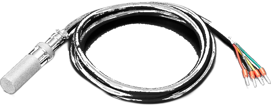
Under fifteen dollars for the plain build, a little more if you want the sensor weatherproofed, and nothing you have to solder if you buy a breakout with header pins already on it:
The sensor wants a spot that sees the air you care about: shaded, out of a direct draft, not touching a warm surface, and not tucked inside the same box as the ESP32, which makes its own heat.
Wire it up.
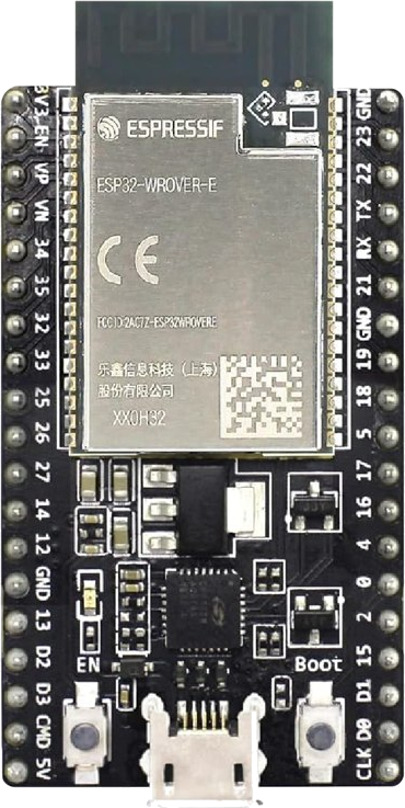
Four wires, and the pin numbers are chosen for you. Power off while you wire:
| On the sensor | Wire color | On the ESP32 | Note |
|---|---|---|---|
| VIN / VCC | red | 3V3 | Always 3V3. Never the board's other power pin. |
| GND | black | GND | Either GND pin. |
| SDA | green on the 4099, white on the 5064 | GPIO 21 | The data line. |
| SCL | yellow | GPIO 22 | The clock line. |
| ADDR | no wire on a cabled probe | leave it alone | Only used for a second sensor. |
About those colors. They belong to the cable, not to the chip, so read them as the common case rather than a law. On the two cabled Adafruit parts, red is power and black is ground on both, and yellow is always the clock. Data is the one that moves: green on the 4099 (sometimes blue on an older run), white on the 5064. Adafruit warns that a few cables leave the factory with data and clock swapped, so if the node finds nothing, swap the yellow and the data wire between pins 21 and 22 and try again. Nothing on this bus is damaged by having those two the wrong way round. A pin-header breakout has no wires at all: the pads are printed, so match VIN to 3V3, GND to GND, SDA to 21 and SCL to 22 by label.
The pin pair, by board
- Classic ESP32 SDA 21, SCL 22
- ESP32-S3 SDA 8, SCL 9
- ESP32-C3 SDA 6, SCL 7
- ESP32-C6 SDA 23, SCL 22
Why the C3 is not on 8 and 9
- The Arduino core's default pair on the C3 is 8 and 9, and both are strapping pins on that chip.
- An I2C bus idles high through its pull-ups, which is the state those pins are read in at power-on.
- So the node defaults to 6 and 7 there, and refuses 2, 8 and 9 with the reason. The S3 and C6 defaults are their cores' own pairs, which are safe.
Why 21 and 22 on the classic, and not any other pair. Most of a classic ESP32's pins are already committed, and the wrong choice fails in ways that look exactly like a broken sensor. Pins 6 through 11 are wired to the flash chip the firmware itself runs from: touch them and the board will not start. Pins 0, 2, 12 and 15 are read at power-on to decide how the chip boots, and a sensor bus sits at a high voltage when it is idle, which is the same nudge that sends the board into the wrong mode. Pins 1 and 3 are the USB console, so using them silences the log you need when something goes wrong. Pins 34 to 39 can only listen, never speak, and this bus needs both. That leaves 21 and 22, which are free, are what the ESP32 expects for this kind of sensor out of the box, and are what the other wired sketches here already use. One wiring habit across the whole library, and both pins are changeable on the setup page if your board is laid out differently.
Flash it.
Plug the board in and press the button. The installer reads the chip on the wire and refuses to write if it isn't the board this image is for, so there is nothing to get wrong.
If the board won't take the flash, or it restarts over and over
Hold the BOOT button down while you plug the USB cable in. Let go once it is plugged in, then press the install button above. That is the whole fix, and it is worth trying first any time a board is being stubborn.
Here is what is going on. A board with no working firmware on it restarts several times a second, forever, because it looks for a program to run and finds nothing. The installer needs the board to hold still long enough to write a megabyte and a half, and it cannot get hold of one that keeps restarting. Holding BOOT as the power arrives puts the chip into the loading mode it was built with, where no program runs at all, so there is nothing to restart and the installer gets a still target.
If you have a serial monitor open, you will know it worked because the scrolling stops. Quiet is what you want.
You may also see invalid header: 0xffffffff repeating in the monitor. That reads like damage and it is not: it is what an empty chip looks like, which is exactly where a board lands if a write was interrupted. The board is fine. Flash it again with BOOT held and it will come back.
If it flashes and runs fine on its own but fails the moment the sensor is connected, suspect whatever sits between them before you suspect either one. A screw-terminal carrier, an adapter board or a breakout is a component too, and a bridged or cracked terminal on one will stop the board booting while the sensor and the ESP32 are both perfectly good. Detaching the sensor is the quickest test: if the board comes back to life, neither it nor the sensor is at fault, and the thing in the middle is where to look. That exact fault cost us most of a night.
Two other things are worth checking before you decide a board is bad. Use a data USB cable, since a charge-only cable carries power but no signal and gives you the same symptoms. And plug straight into the computer rather than through a hub, because a write that browns out part way through leaves the board empty in just this way.
You'll need a data USB cable (not charge-only) and Chrome or Edge on a computer. A classic ESP32 talks to your computer through a separate USB chip, so the first time you plug one in you may need to install its driver once: look for CP2102 or CH340 printed near the USB socket, then fetch that driver. Once it's flashed, set it up from any phone or laptop.
Prefer the source? Browse it on GitHub: the full project, openly licensed, ready to build yourself.
Set it up.
All the setup happens on the device's own page. Nothing to install, and it works with no internet, which is what you want if you flashed a few at the extension office to take home.
- Power the node from any USB charger or your computer.
- On your phone or laptop, join the Wi-Fi network
OAT-Setup-XXXXXX(open, no password). A setup page opens by itself; if not, visithttp://192.168.4.1. - Sign in, then fill in the device name, your Farm ID, the location, your Wi-Fi, and where the readings should go. Press Save & Connect. It joins your Wi-Fi right away and shows you its new address, no reboot, no hunting for it.
- Open the node's Status page. The current temperature and humidity are right there, in large type: that is your proof the wiring is right. Then press Send a test reading and look for the green confirmation that your endpoint received it.
The setup network stays on, so you can rejoin any time to change a setting, and your settings survive reboots. A fresh firmware flash wipes them clean, on purpose, so a re-used board never carries the last owner's Wi-Fi or endpoint.
Two knobs are worth understanding. Read the sensor every is how often it takes a reading; push interval is how often it sends. Every reading taken inside a push window is averaged into the number that gets sent, so reading every 10 seconds and pushing every minute gives you a steadier figure than reading once a minute, at no extra cost. There are also offsets for temperature and humidity, added to every reading, for lining this node up against a reference you trust.
The two pin fields will refuse a pin that cannot work, and tell you why. That is deliberate: a pin setting is remembered and re-applied every time the board powers on, so a wrong one is not a mistake you get to notice and correct. Some of them would stop the board booting at all, taking the setup page with them.
If the setup network is being fussy, everything above is also reachable over the USB console: type help for the list, or go straight to wifi, endpoint, name, and read.
Ready to test it? Enter https://iot-test.openagriculturetechnology.com/ingest as the
endpoint URL on the setup page, then open the
Open Agriculture Technology Test Endpoint
and pick your farm, the gateway name you gave the node: your gateway and its sensors show up live,
readings, charts and heartbeat, no account needed. It keeps about an hour of readings, enough to prove
the chain works before you point the node at an endpoint you keep. Prefer a message-by-message check?
The conformance sandbox shows each POST checked against the
standard.
Open the printable setup card (PDF)
A three-page field card: what to have on hand, the flash and setup steps, blanks for this node’s settings and probe serials, the console commands, and the fixes for the usual snags. Print one per node.
Two sensors, one node.
An SHT-30 answers to one of two addresses on the bus, decided by its ADDR pin, which means a single board can carry two of them on the same four wires. Leave the first sensor's ADDR pin alone and connect the second one's to 3V3. Wire both to the same SDA, SCL, 3V3 and GND.
Each sensor reports under its own serial, so you get two genuinely separate readings out of one node: inside and outside a hoop house, floor and canopy, the supply air and the room. The node finds whichever sensors are present when it starts, so there is no setting to get wrong, and the status page shows you both. Which serial is which place is recorded at your endpoint, not on the device.
Two is the limit, and it is the chip's limit rather than ours. A third SHT-30 has no address left to answer on.
One catch if you bought a cabled probe: four wires out means the address pin never leaves the sealed end, and it is fixed at the first address. So two probes cannot share a node, but a probe and a breakout can, with the breakout's ADDR pin tied to 3V3.
Knowing you can trust it.
A wired sensor's real failure is almost never the sensor. It is the wire: a tug on the cable, damp in a connector, a run that got extended one too many times. That failure is worth designing for, because the dangerous version of it is not a node that goes silent, it is a node that keeps reporting numbers that happen to be wrong.
So every reading arrives with a checksum, and the node checks it and throws the reading away if it doesn't match. A gap in your data is honest. A plausible wrong number is not. After several failures in a row the node rebuilds its connection to the sensor and resets it, which recovers a confused wire without anyone driving out to power-cycle a box. And if the sensor stops answering altogether, the status page stops showing its last reading and tells you when it was last heard from instead: a number from two hours ago, displayed as though it were current, is its own kind of lie.
The status page and the console both show the running counts: readings good, readings failed, checksums failed, and how many times the connection had to be rebuilt. That is how you answer "is my wiring actually alright?" instead of guessing.
Meanwhile the node sends a small heartbeat every 60 seconds whatever else is happening. So when a sensor dies the heartbeats keep arriving while the readings stop, and your endpoint can tell the difference between alive but quiet and gone. That distinction is the reason the heartbeat is sent first, before the readings, every cycle.
One more piece of the same habit: each push says how long a stretch its average actually covers. The node keeps reading whether or not the network is up, so the first message after an outage can carry hours of readings, and it says hours rather than repeating the setting you typed.
What it sends.
Two kinds of message, both tiny, and both the same shape every other node in this library sends. Every cycle a batch of readings in canonical units (°C and %RH) so the receiver never has to guess; every 60 seconds a lean heartbeat about the node's own health. Both carry a schema tag (oat-ods/0.3) so you can route and version them:
See the two message types
A batch of readings, sent every cycle:
{
  "schema": "oat-ods/0.3",
  "msg_type": "batch",
  "sent_at": "2026-07-25T14:26:00Z",
  "seq": 3000004,
  "source": { "tier": "oat-sht30-node", "gateway_id": "gh2-north",
              "farm_id": "riverbend-farm",
              "fw": "OAT-SHT30-Node/2.0.4" },
  "messages": [
    { "observed_at": "2026-07-25T14:26:00Z",
      "stream": { "id": "sht30:0a1b2c3d",
                  "location": "Greenhouse 2 / North bench" },
      "measurement": "temperature", "value": 23.41, "unit": "Cel",
      "agg": { "window_s": 60, "samples": 6, "method": "mean" },
      "source": { "physical_id": "sht30:0a1b2c3d",
                  "brand": "Sensirion", "model": "SHT30" } },
    { "observed_at": "2026-07-25T14:26:00Z",
      "stream": { "id": "sht30:0a1b2c3d",
                  "location": "Greenhouse 2 / North bench" },
      "measurement": "humidity", "value": 58.7, "unit": "%RH",
      "agg": { "window_s": 60, "samples": 6, "method": "mean" },
      "source": { "physical_id": "sht30:0a1b2c3d",
                  "brand": "Sensirion", "model": "SHT30" } }
  ]
}
A heartbeat, sent every 60 s, so the endpoint knows the node is alive even when the sensor has stopped answering:
{
  "schema": "oat-ods/0.3",
  "msg_type": "status",
  "observed_at": "2026-07-25T14:26:00Z",
  "state": "online",
  "source": { "tier": "oat-sht30-node", "gateway_id": "gh2-north",
              "farm_id": "riverbend-farm",
              "device_id": "oat-3c8a1fa77d14",
              "fw": "OAT-SHT30-Node/2.0.4" },
  "health": {
    "uptime_s": 315, "boot_count": 2, "reset": "poweron",
    "free_heap": 214800, "min_free_heap": 203600, "largest_block": 110592,
    "rssi": -68, "wifi_reconnects": 0, "push_ok": 5, "push_fail": 0,
    "transport": "https", "tls_ok": true, "chip": "ESP32",
    "temp_c": 54.4, "loops_per_sec": 1120,
    "lan_ip": "192.168.1.37", "ssid": "BarnWiFi", "mdns": "oat-gh2-north.local"
  }
}
The physical_id is the sensor chip's own serial number, read off the part at startup. The stream.id is that same serial, because the node names nothing: your endpoint (or Home Assistant) is where that serial becomes a place. That split is the point: swap a failed sensor for a new one, tell the endpoint the new serial belongs to the same spot, and its history carries straight on, with the change of hardware visible in the record.
Want the whole format, both message types, every field, and the full measurement vocabulary? See the developer reference, or read the machine-readable JSON Schema.
For makers & trainers.
Frequently asked questions.
Which ESP32 pins should I use for an SHT-30?
On a classic ESP32, use GPIO 21 for SDA and GPIO 22 for SCL, with the sensor powered from 3V3 and GND. These are the chip's default I2C pins and they avoid every committed pin: GPIO 6 to 11 are wired to the SPI flash, GPIO 0, 2, 12 and 15 are strapping pins that an idle-high I2C bus can pull into the wrong boot mode, GPIO 1 and 3 are the serial console, and GPIO 34 to 39 are input-only with no pull-ups, so they cannot drive a bidirectional bus at all. On an ESP32-S3 use 8 and 9, on an ESP32-C6 use 23 and 22, and on an ESP32-C3 use 6 and 7, because the C3's usual 8 and 9 are strapping pins on that chip.
What do the wire colors mean on an SHT-30 sensor cable?
On the common Adafruit cabled sensors, red is power, black is ground, and yellow is the I2C clock. The data wire is the one that varies by part: green on the mesh-protected weatherproof probe (Adafruit 4099, occasionally blue on an older run) and white on the sealed shell version (Adafruit 5064). Wired to a classic ESP32 that means red to 3V3, black to GND, yellow to GPIO 22, and the green or white data wire to GPIO 21. Colors are a cable convention rather than a standard, and a small number of cables ship with data and clock swapped, so if nothing is detected, swap those two wires between GPIO 21 and 22. Reversing them causes no damage.
How accurate is an SHT-30 compared to a cheap wireless thermometer?
Sensirion's SHT3x-DIS datasheet specifies the SHT30 at a typical tolerance of plus or minus 2 percent relative humidity at 25 degrees Celsius, and plus or minus 0.2 degrees Celsius on temperature between 0 and 65 degrees Celsius. A typical consumer Bluetooth thermometer is specified around plus or minus 0.5 degrees Celsius and 3 to 5 percent humidity, so the SHT-30 is the better part, though the honest comparison is closer than it looks: a cabled SHT-30 probe is an assembly, and Adafruit rates its sealed versions at plus or minus 0.5 degrees Celsius rather than the bare chip's 0.2. The wired sensor's real advantages are that it has no battery to die, no radio link to lose, and it sits exactly where you put it.
Can two SHT-30 sensors share one microcontroller?
Yes, two. The SHT-30 has an address-select pin that chooses between the addresses 0x44 and 0x45, so two sensors can share the same pair of data wires: leave one sensor's address pin unconnected and tie the other's to 3.3 volts. Two is the hard limit, because a third sensor has no remaining address to answer on. Reading more than two air sensors from one board needs a different approach, such as an I2C multiplexer.
Why does my SHT-30 read nothing at all?
In order of likelihood: no power or ground, SDA and SCL swapped, or missing pull-up resistors. Nearly every SHT-30 breakout board includes the pull-ups, but a bare sensor chip does not and needs a resistor of 4.7k to 10k from each line to 3.3 volts. A bus scan is the fastest diagnostic, because it shows whether anything on the wires answers at all.
Should I use the SHT-30's built-in heater?
Only where the sensor sits in condensing air, such as a greenhouse that reaches 100 percent humidity overnight, because a wet sensor reads saturated regardless of the actual air. The heater drives that moisture off. Leave it off otherwise: a heater next to a temperature sensor produces readings that are warmer and drier than the air, so any reading taken during a heater pulse, and for a settling period afterward, has to be discarded rather than reported.
Where does the data from a DIY sensor node go?
Only to the endpoint configured on the device. A node running open firmware pushes each reading to whatever destination you enter during setup: your own webhook, your own MQTT broker, a hub such as Home Assistant, or a cloud service you choose. Nothing is transmitted anywhere else, and the destination can be changed later in the device's settings.