

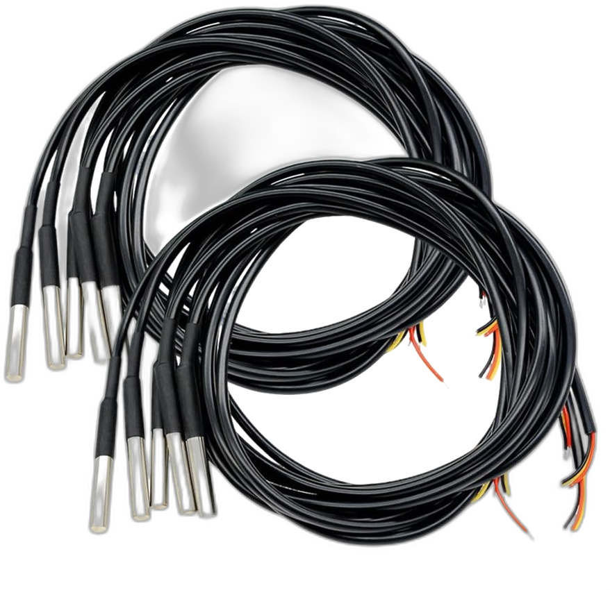
A stainless probe on a cable, sealed, cheap, and happy in a freezer, a brine tank or a compost pile. What makes it worth a page of its own is the wire: every DS18B20 carries its own address, so a dozen probes share one data line and one pin on the board, and each still reports as itself. One node, one cable run, the whole cold room.
Everything after the wiring is settled on a form the device serves itself, from a phone standing in the doorway of the cold room. Where the readings go is your decision and stays your decision. A few dollars a probe, doing the one thing worth doing with a sensor: turning a real place into a number you own.
What it does.
This node finds every DS18B20 on its wire at startup, reads them all on a cadence you choose, averages each probe's readings across the push window, and sends temperature per probe to an endpoint you own: your own webhook, an MQTT broker you run, Home Assistant, or Open Agriculture Technology.
Here is what the part is actually specified to do. These are the manufacturer's numbers, copied from the sheet rather than rounded off by us:
| Parameter | Value |
|---|---|
| Accuracy | ±0.5 °C from −10 to +85 °C |
| Accuracy, full range | ±2 °C from −55 to +125 °C |
| Measuring range | −55 to +125 °C |
| Resolution | 9 to 12 bits, your choice: 0.5 °C down to 0.0625 °C |
| Conversion time | 93.75 ms at 9 bits · 750 ms at 12 bits |
| Address | a unique 64-bit code per probe, lasered in at the factory |
| Interface | 1-Wire: one data line, shared by every probe on the run |
| Measures | temperature, and nothing else |
Two things to take from that table. It is a half-degree part, not a tenth-degree part. Twelve-bit resolution reports hundredths, but resolution is not accuracy: the number moves in steps of 0.0625 °C and is specified to within half a degree of the truth. For a freezer alarm or a compost curve that is plenty; for a calibration reference it is not. Away from the middle of its range it is looser still, ±2 °C at the extremes, which is worth knowing if you are measuring a blast freezer rather than a walk-in.
Read it yourself rather than taking our word for it: the DS18B20 datasheet puts the accuracy in its first paragraph and the resolution table in its Configuration Register section.
It reads the older DS18S20 too. A great many probes in the field are the earlier part, and plenty of multi-packs sold as DS18B20 contain them. They share the wire, the search and the checksum; they differ in that they report 9 bits in half-degree steps, with the finer detail recovered from a pair of count registers, and they have no resolution setting. The node tells them apart by their family code, decodes each correctly, and labels the reading with which one it came from. Nothing for you to set.
It reports what it measured and nothing more. That is the Collect layer at its plainest: a real number out of a real place, reliably, into somewhere that belongs to you.
See it in action: the Open Agriculture Technology Test Endpoint is live right now, our own gateways pushing readings, and yours can join them in minutes.
One wire, many probes.
Most sensors need a bus to themselves or an address you set with a solder blob. A DS18B20 does neither. Every one ever made carries a unique 64-bit address, burned in with a laser at the factory: a family code that says "I am a DS18B20", a 48-bit serial that is that chip alone, and a checksum over both. No two are the same, anywhere, ever.
That is what lets them share a wire. The node starts up and runs a search: it asks every device on the line to shout its address one bit at a time, and walks the tree of answers until it has enumerated all of them. Nothing to configure, nothing to count. Wire one probe or wire nine, and the node reports what it found.
So how many can you actually run? Honest answer: more than you probably need, and fewer than the marketing suggests. The protocol never runs out of addresses. What runs out is signal. Each probe and each metre of cable adds a little capacitance, and the bus talks in pulses about sixty microseconds long, so past a certain point the edges get too soft to read and you start seeing checksum failures rather than a clean stop. On a bench or a single cold room, on the standard resistor, eight to ten probes is comfortable. This node caps its list at ten and says so on the console when the list fills: a bound we chose, not one the chip imposes.
Beyond that, the fixes are the ones any 1-Wire network uses: a stiffer pull-up (2.2 k), a run that goes out and back as one line rather than branching like a star, and eventually an active pull-up chip. If you are wiring a barn rather than a room, that is real engineering rather than a jumper wire, and the manufacturer's application note on long 1-Wire networks is where to start.
Each probe reports under its own factory address, and that is what arrives at your endpoint: ds18b20:28f39296f0013cbd, not "sensor 1". The node names nothing, on purpose. Which probe sits on which shelf is a decision that belongs where it can be edited without a trip to the barn and where it survives a firmware update, and that is the endpoint. We collect and push; the endpoint maps the address to a place and shows you a name.
What you need.
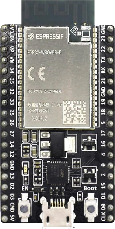
Under fifteen dollars for a one-probe node, and a few dollars a probe after that. Nothing to solder if you buy probes on cable and a board with header pins:
The probe can sit in the cold, in the wet, in the tank. The board cannot: keep it somewhere dry on USB power, in a sealed box if the spot is damp or dusty, and run the cable to the sensor rather than the sensor to the board.
Wire it up.
Three wires and one resistor. Every probe on the run connects to the same three wires. Power off while you wire:
| On the probe | Wire color | On the ESP32 | Note |
|---|---|---|---|
| VDD | red | 3V3 | Always 3V3. Never the board's other power pin. |
| GND | black | GND | Either GND pin. |
| DQ (data) | yellow | the data pin, below | Plus the 4.7 k resistor from this line up to 3V3. |
About those colors. They belong to the cable, not the chip. Nearly every sealed DS18B20 probe on the market uses red for power, black for ground and yellow for data, and that is what the photograph at the top of this page shows. A few use white or blue for the data wire instead; if yours does, the odd one out is the data line. A bare three-legged chip has no wires at all: with the flat face towards you and the legs down, the pins are ground, data, power, left to right.
Which pin on the board. One data pin carries the whole bus, and the default differs by chip because the pins you must not use differ by chip:
| Board | Default | Why |
|---|---|---|
| ESP32 (classic) | GPIO 4 | Free: not the flash, not a strapping pin, not input-only. |
| ESP32-S3 | GPIO 4 | Free. |
| ESP32-C3 | GPIO 4 | Free. |
| ESP32-C6 | GPIO 6 | On a C6, GPIO 4 is a strapping pin, so it gets a different default. |
That last row is the whole reason the defaults are not identical. A 1-Wire bus sits high when it is idle, held there by the resistor, and a strapping pin is read at power-on to decide how the chip boots. Put the bus on one and the board can come up in the wrong mode, which looks like a dead board rather than a wiring mistake. The setup page will refuse a pin that cannot work and tell you why: the flash pins the firmware itself runs from, the strapping pins, the USB pins, the console pins, and on a classic ESP32 the input-only pins that can never talk back. That refusal matters because a pin setting is remembered and re-applied at every boot, so a wrong one is not a mistake you get to notice and correct.
The resistor, and why it is not optional.
This is the one part people leave out, and the node cannot work without it.
A 1-Wire bus is what electronics calls open drain. Every device on the line, including the board, can only ever pull the wire down to ground. Nothing pushes it back up. The resistor is the thing that pulls it back up: a weak, constant tug towards 3.3 V that lets go the instant anything pulls down. That push-pull is how a single wire carries conversation in both directions.
Leave it out and there is no bus at all, only a floating pin picking up whatever is in the air. The node will report no sensor, or worse, it will read something and the checksum will throw it away, which looks exactly like a broken probe. Fitting a resistor is a two-minute job that saves an evening.
One more thing the resistor decides. A DS18B20 can be run on just two wires, stealing its power from the data line between conversations, a trick called parasite power. It works, but a conversion then needs the board to clamp the line high with a much stronger pull-up for the whole conversion, and a node that gets that wrong publishes a fixed 85 °C forever. This node powers its probes properly from 3V3 and does not do parasite mode. It does detect it: if you leave the red wire off, the status page says so plainly instead of pretending the readings are fine.
Flash it.
Plug the board in and press the button for your board. The installer reads the chip on the wire and refuses to write if it isn't the board that image is for, so there is nothing to get wrong.
If the board won't take the flash, or it restarts over and over
Hold the BOOT button down while you plug the USB cable in. Let go once it is plugged in, then press the install button above. That is the whole fix, and it is worth trying first any time a board is being stubborn.
Here is what is going on. A board with no working firmware on it restarts several times a second, forever, because it looks for a program to run and finds nothing. The installer needs the board to hold still long enough to write a megabyte and a half, and it cannot get hold of one that keeps restarting. Holding BOOT as the power arrives puts the chip into the loading mode it was built with, where no program runs at all, so there is nothing to restart and the installer gets a still target.
If you have a serial monitor open, you will know it worked because the scrolling stops. Quiet is what you want.
You may also see invalid header: 0xffffffff repeating in the monitor. That reads like damage and it is not: it is what an empty chip looks like, which is exactly where a board lands if a write was interrupted. The board is fine. Flash it again with BOOT held and it will come back.
If it flashes and runs fine on its own but fails the moment the sensor is connected, suspect whatever sits between them before you suspect either one. A screw-terminal carrier, an adapter board or a breakout is a component too, and a bridged or cracked terminal on one will stop the board booting while the sensor and the ESP32 are both perfectly good. Detaching the sensor is the quickest test: if the board comes back to life, neither it nor the sensor is at fault, and the thing in the middle is where to look. That exact fault cost us most of a night.
Two other things are worth checking before you decide a board is bad. Use a data USB cable, since a charge-only cable carries power but no signal and gives you the same symptoms. And plug straight into the computer rather than through a hub, because a write that browns out part way through leaves the board empty in just this way.
You'll need a data USB cable (not charge-only) and Chrome or Edge on a computer. A classic ESP32 talks to your computer through a separate USB chip, so the first time you plug one in you may need to install its driver once: look for CP2102 or CH340 printed near the USB socket, then fetch that driver. The S3, C3 and C6 have USB built into the chip and need no driver at all. Once it's flashed, set it up from any phone or laptop.
Prefer the source? Browse it on GitHub: the full project, openly licensed, ready to build yourself.
Set it up.
All the setup happens on the device's own page. Nothing to install, and it works with no internet, which is what you want if you flashed a few at the extension office to take home.
- Power the node from any USB charger or your computer.
- On your phone or laptop, join the Wi-Fi network
OAT-Setup-XXXXXX(open, no password). A setup page opens by itself; if not, visithttp://192.168.4.1. - Sign in, then fill in the device name, your Farm ID, the location, your Wi-Fi, and where the readings should go. Press Save & Connect. It joins your Wi-Fi right away and shows you its new address, no reboot, no hunting for it.
- Back on the setup page, every probe the node found is listed with its own address and its current reading. Note down which address is which place: pinch a probe in your fingers and watch its number climb, and that is the one you are holding. You will want that list when you set the node up at your endpoint.
- Open the node's Status page, press Send a test reading, and look for the green confirmation that your endpoint received it.
That trick in step four is the whole answer to "which probe is which", and it is worth doing before you seal anything up. Warm one probe in your hand, refresh, and the one that moved is the one you are holding. Write the address down next to the place; that pairing is what you will type in at your endpoint once, and it is the only place it needs to live.
Add a probe later and nothing needs reflashing: wire it onto the same three wires and press re-scan for probes. It appears with its own address and starts reporting immediately. Probes are listed in address order, so the list does not shuffle when you add one.
Two knobs are worth understanding. Read the sensor every is how often it takes a reading; push interval is how often it sends. Every reading taken inside a push window is averaged into the number that gets sent, so reading every 10 seconds and pushing every minute gives you a steadier figure than reading once a minute, at no extra cost. There is also a resolution setting, 9 to 12 bits: twelve is the default and takes three quarters of a second per conversion, nine is coarse and nearly instant. On a cold room, twelve.
If the setup network is being fussy, everything above is also reachable over the USB console: type help for the list, or go straight to wifi, endpoint, name, read, bus and rescan.
Ready to test it? Enter https://iot-test.openagriculturetechnology.com/ingest as the
endpoint URL on the setup page, then open the
Open Agriculture Technology Test Endpoint
and pick your farm, the gateway name you gave the node: your gateway and its probes show up live,
readings, charts and heartbeat, no account needed. It keeps about an hour of readings, enough to prove
the chain works before you point the node at an endpoint you keep. Prefer a message-by-message check?
The conformance sandbox shows each POST checked against the
standard.
Open the printable setup card (PDF)
A three-page field card: what to have on hand, the flash and setup steps, blanks for this node’s settings and probe serials, the console commands, and the fixes for the usual snags. Print one per node.
Knowing you can trust it.
A wired sensor's real failure is almost never the sensor. It is the wire: a tug on the cable, damp in a connector, a run that got extended one too many times. That failure is worth designing for, because the dangerous version of it is not a node that goes silent, it is a node that keeps reporting numbers that happen to be wrong.
So every reading arrives with a checksum, and the node checks it and throws the reading away if it doesn't match. A gap in your data is honest. A plausible wrong number is not. The node also counts "no answer" separately from "bad checksum", because they are different faults: one is a probe that has been unplugged, the other is a bus that is marginal and wants a stiffer resistor or a shorter run.
After several failures in a row the node re-scans the wire, which recovers a probe that was unplugged and put back, or a line that glitched. A re-scan keeps each probe's counters rather than resetting them, because zeroing "reads failed" in the middle of the fault the re-scan exists to fix would hide the one thing worth seeing. And if a probe stops answering altogether, the status page stops showing its last reading and tells you when it was last heard from instead: a number from two hours ago, displayed as though it were current, is its own kind of lie.
Meanwhile the node sends a small heartbeat every 60 seconds whatever else is happening. So when a probe dies the heartbeats keep arriving while the readings stop, and your endpoint can tell the difference between alive but quiet and gone. That distinction is the reason the heartbeat is sent first, before the readings, every cycle.
One more piece of the same habit: each push says how long a stretch its average actually covers. The node keeps reading whether or not the network is up, so the first message after an outage can carry hours of readings, and it says hours rather than repeating the setting you typed.
What it sends.
Two kinds of message, both tiny, and both the same shape every other node in this library sends. Every cycle a batch of readings in canonical units (°C) so the receiver never has to guess; every 60 seconds a lean heartbeat about the node's own health. Both carry a schema tag (oat-ods/0.3) so you can route and version them:
See a batch from a two-probe node
{
  "schema": "oat-ods/0.3",
  "msg_type": "batch",
  "sent_at": "2026-07-25T14:26:00Z",
  "seq": 3000004,
  "source": { "tier": "oat-ds18b20-node", "gateway_id": "walkin-1",
              "farm_id": "riverbend-farm",
              "fw": "OAT-DS18B20-Node/2.0.4" },
  "messages": [
    { "observed_at": "2026-07-25T14:26:00Z",
      "stream": { "id": "ds18b20:28ff641f8c1a3b02",
                  "location": "Walk-in cooler" },
      "measurement": "temperature", "value": 3.44, "unit": "Cel",
      "agg": { "window_s": 60, "samples": 6, "method": "mean" },
      "source": { "physical_id": "ds18b20:28ff641f8c1a3b02",
                  "brand": "Analog Devices", "model": "DS18B20" } },
    { "observed_at": "2026-07-25T14:26:00Z",
      "stream": { "id": "ds18b20:28ff0c2b7d1e4a11",
                  "location": "Walk-in cooler" },
      "measurement": "temperature", "value": 2.19, "unit": "Cel",
      "agg": { "window_s": 60, "samples": 6, "method": "mean" },
      "source": { "physical_id": "ds18b20:28ff0c2b7d1e4a11",
                  "brand": "Analog Devices", "model": "DS18B20" } }
  ]
}
Both stream.id and physical_id are the probe's own factory address, read off the wire at startup, because the node names nothing. location is what you typed at setup, and it describes the node rather than an individual probe. Which probe sits on which shelf is recorded once at your endpoint, where it survives a firmware update and can be edited without a trip to the cold room, and where swapping a failed probe is one line changed rather than a device visit. The farm_id above it groups every node a grower owns.
Want the whole format, both message types, every field, and the full measurement vocabulary? See the developer reference, or read the machine-readable JSON Schema.
For makers & trainers.
Frequently asked questions.
How many DS18B20 sensors can I put on one pin?
The 1-Wire protocol sets no limit, because every DS18B20 has a unique 64-bit address burned in at the factory and the master addresses each one individually. The real limit is electrical: each sensor and each metre of cable adds capacitance that softens the edges of a 60 microsecond pulse. On a short run with the standard 4.7k pull-up resistor, eight to ten sensors is comfortable. More than that, or a long run, needs a stiffer 2.2k pull-up, a linear cable layout rather than a star, and eventually an active pull-up. This firmware caps its own list at ten, which is a bound chosen for the same electrical reason rather than a limit of the chip.
Why does a DS18B20 need a 4.7k resistor?
Because 1-Wire is an open-drain bus: every device can only pull the data line down to ground, and nothing pulls it back up. The 4.7k resistor between the data line and 3.3 volts is what pulls it up, so the line can return high between pulses. Without it the pin floats and reads noise, which looks exactly like a broken sensor. Fit one resistor for the whole bus, not one per sensor. Many probe modules and breakout boards have it fitted already; a bare chip or plain cable does not. If reads are intermittent on a long run or with several sensors, a stiffer 2.2k resistor is the first thing to try.
What do the wire colors mean on a DS18B20 probe?
On nearly every sealed stainless DS18B20 probe, red is power, black is ground, and yellow is the data line. Wired to an ESP32 that means red to 3V3, black to GND, and yellow to the data pin, with the 4.7k resistor between the yellow line and 3V3. A few probes use white or blue for data instead of yellow; on those, the odd colour out is the data wire. A bare three-legged DS18B20 chip has no wires: with the flat face towards you and the legs pointing down, the pins are ground, data and power from left to right.
Why does my DS18B20 read 85 degrees?
Because 85.00 degrees Celsius is the power-on value of the DS18B20's temperature register, not a measurement. Seeing it means the sensor reset or the conversion never completed, so the register was never written with a real reading. The usual causes are a sensor running on parasite power without the strong pull-up a conversion needs, a supply that browns out mid-conversion, or a missing VDD wire. This node discards an exact 85 rather than publishing it, and counts the discards, because a rising count is the clearest sign that the wiring needs attention.
How accurate is a DS18B20?
The datasheet specifies plus or minus 0.5 degrees Celsius between minus 10 and plus 85 degrees, widening to plus or minus 2 degrees across the full minus 55 to plus 125 degree range. Resolution is a separate thing from accuracy: at 12 bits the reading moves in steps of 0.0625 degrees, which is finer than the part is accurate. That is plenty for a freezer alarm, a cold room, a compost curve or a brine tank, and not enough for a calibration reference.
Can a DS18B20 go in water?
The sealed stainless probe version can: the tip is a metal tube with the chip potted inside, and it is designed to sit in liquid. That is the version to buy for a tank, a brine bath or a hydroponic reservoir. The bare three-legged chip cannot, and neither can the cable joint on a cheap probe if it is submerged permanently, so keep the join out of the liquid. The board itself must stay dry regardless: run the cable to the probe, not the probe to the board.
Where does the data from a DIY sensor node go?
Only to the endpoint configured on the device. A node running open firmware pushes each reading to whatever destination you enter during setup: your own webhook, your own MQTT broker, a hub such as Home Assistant, or a cloud service you choose. Nothing is transmitted anywhere else, and the destination can be changed later in the device's settings.